
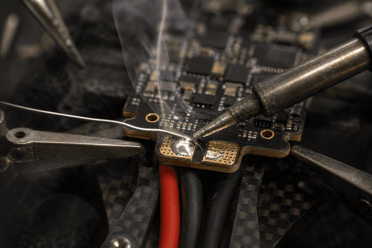
Soldering ESCs and pads without lifting traces

Lifting a pad on a flight controller or ESC is one of the fastest ways to turn a ₹500 repair into a ₹5,000 reorder. Good soldering is boring, that is the point. Fast, confident joints with strain relief beat artistic blobs every time.
Iron and tip
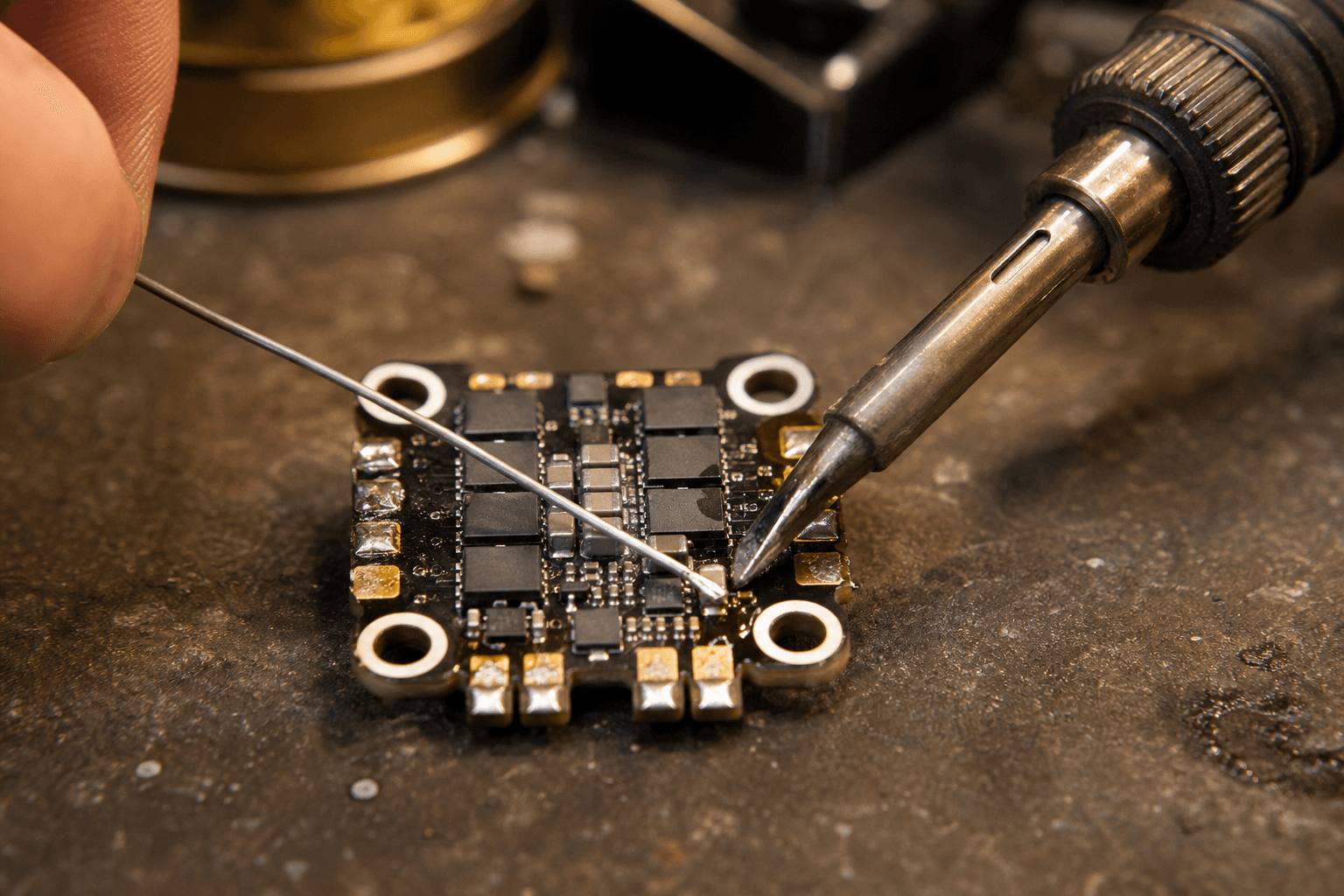
- Temperature: most 63/37 leaded work sits around 350–380 °C on a adjustable station; lead-free needs hotter and more skill.
- Tip: chisel or hoof just wide enough for the joint, not a screwdriver tip cooking the whole pad.
- Clean tip: wipe often; dull grey tips transfer heat poorly and dwell longer (bad for pads).
Station vs pencil iron
A temperature-controlled station pays for itself on first saved FC pad. Pencil irons without control tend to idle cool and spike hot, both bad for fine SMD pads.
Tip sizing
| Joint type | Tip approach |
|---|---|
| Motor wire to ESC pad | Chisel just wider than pad |
| XT60 power lead | Larger hoof, heat pin fast |
| Signal wires to FC | Fine chisel, minimal dwell |
Flux is not optional
Use flux appropriate for your wire, gel flux for motor wires, no-clean for many FC jobs if you are disciplined about residue near gyros. Flux lets you make the joint fast. Slow cooking lifts pads.
Residue near gyros
No-clean flux near FC gyro area is acceptable on many builds if you do not flood the board. Avoid conductive flux types on signal pads. Wipe excess if the manufacturer recommends.
Common mistake: Dry iron on oxidized pad, pushing harder instead of adding flux.
The joint that does not lift pads
- Tin the pad lightly: do not flood; a thin shine is enough.
- Pre-tin motor wire: heat the wire, not the pad, for the merge.
- Touch wire to pad, heat the wire: solder flows to heat; seconds, not minutes.
- Remove iron and hold still: one wiggle can shear a via.
For through-hole standoffs, heat the pin, not the ring around it, until solder wicks through.
Motor wire joint step-by-step
Motor to ESC pad:
1. Flux pad lightly
2. Tin pad, thin film only
3. Strip wire, twist lightly, flux wire
4. Tin wire end away from pad
5. Wire on pad, heat wire until flow
6. Iron off, hold 2 seconds still
7. Inspect, shiny, not grey ball
8. Strain relief to standoff before arm channel
See motor wire routing for service loop discipline.
Strain relief saves pads
Motor wires pulling on pads lift them on crash #3, not crash #1. Route wires:
- Short paths off ESC pads
- Service loop before entering arm channel
- Zip tie to standoff, not dangling from the joint
See crash repair triage for when a lifted pad means bench time.
What strain relief is not
A giant solder blob adding mass is not strain relief. Zip tie the wire, not the joint, to structural standoffs.
XT60 and power joints
Power joints need heat on the pin inside the housing, not the plastic. Cold XT60 joints arc and heat in flight, see connector guide. Secure pigtail to frame so crash torque does not transfer to ESC pads.
Common mistakes
| Mistake | Result |
|---|---|
| Pumping iron up/down on pad | Lifted pad / torn trace |
| Cold joint (grey, grainy) | Resistance, heat, fails in flight |
| Solder blob bridging pads | Magic smoke on arm |
| “I'll fix it with more solder” | Weight + bridges |
Cold joint repair
Do not pile solder. Flux, gentle reheat once, remove iron. If still grey, desolder wick and redo cleanly. Repeated reheat lifts pads.
Desoldering and pad rescue
If pad lifts slightly but trace intact:
- Superglue pad down (community technique), advanced, last resort
- Wire to alternate point per manufacturer repair diagram
- Order replacement board if power pad gone
Know when to stop, see below.
When to stop and order
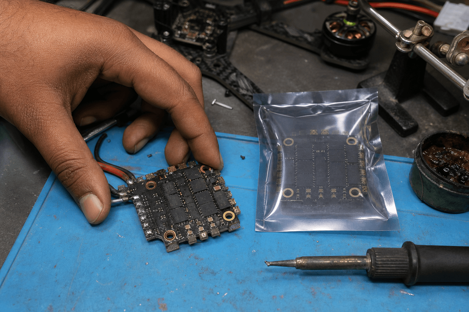
- Pad rings off with copper showing on multiple pads
- Via damaged on a power pad
- ESC MOSFET looks cracked or smells sweet
Bench repairs have a ceiling. Factor that into import vs domestic spare ordering, a local ESC in the drawer beats a two-week wait.
First power after repair
Use smoke stopper, repaired joints fail at load, not at continuity beep.
RX and signal pad caution
Signal pads on FC are smaller and less forgiving than ESC motor pads. Use finer tip, less solder, and magnification if available. UART pads lifted on RX install brick the flight, receiver UART vs SPI planning reduces rework.
Lead-free and RoHS boards
Some newer boards expect lead-free profiles, hotter iron, different flux. If joints look grey on RoHS pads, verify iron temperature before blaming technique. Leaded solder on RoHS can work for repair but know your board policy.
Practice without risking flight FC
Sacrifice an old ESC board for motor pad practice. Flow confidence on junk before touching your only stack.
India bench notes
Ventilate flux fumes, small rooms heat up fast in summer. Iron tips oxidize faster in humid monsoon storage, tin tip before session.
Dwell time guide (seconds, not minutes)
| Joint | Target dwell | Stop sign |
|---|---|---|
| FC signal pad | 1–2 s | Pad moves on pressure |
| ESC motor pad | 2–3 s | Grey grainy blob |
| XT60 pin | 3–4 s | Plastic smell |
| u.fl (avoid if possible) | Expert only | Pad lifts off FC |
If you are counting past five on a motor pad, remove iron, add flux, let pad cool, try once more. Repeated heat is how pads die.
Bench session workflow
1. Tin tip, set temp, flux ready, smoke stopper on bench
2. Sacrifice board or practice pads first if rusty
3. Power joints before signal pads, confidence order
4. Strain relief before moving to next arm
5. Continuity + smoke stopper before props ever spin
6. Photo finished stack, wire colours before heat shrink hides them
One focused hour beats three distracted evenings that lift the same pad twice.
Magnification and lighting
You do not need a microscope. A desk lamp and phone zoom photo after each joint catches bridges before arm day. Indian evening light in a balcony workshop is often too dim to see cold joints, fix the light before fixing the solder.
Bench
- Control / F7, replacement ESC/FC when pads lift
- the Bench, bench consumables
See also
- Crash repair triage, field vs bench decisions
- Building a field repair kit, iron, flux, and consumables to carry
- Connector guide: XT60, XT30, PH2.0, BT2.0, power plugs that fail next to solder joints
Discussion
Comments aren't open on this post yet. Share it with your build group, or start a thread on X.